
Cooler PCBs for a Cooler Planet
PCBs aren’t coal-fired power plants, but they’re everywhere, so keeping them cool keeps us all a little cooler.
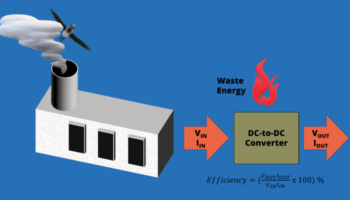
Wasted energy burns off as heat. That energy comes from a power plant or a battery. And worse, if energy burns off inside a building, air conditioning burns even more energy to keep workers and machines cool. Less waste heat usually means better products too. As we engineers know – the best designs are also the most efficient.
Power supplies on a Printed Circuit Board
Once upon a time, a single logic supply, such as +5V, was often the only device power on a PCB. Not anymore, because:
- FPGAs, IOT modules and many other devices support multiple (often configurable) IO standards and these need a variety of supply voltages
- Many devices, including DDR 3/4/5 SDRAM, have core supply voltages that are distinct from their IO supplies. DDR4 also needs a separate Wordline Boost supply
- Increasingly, analog and RF circuits share a PCB alongside digital. These supplies need careful distribution as well as separate supply voltages
- End-of-bus termination, for example, Address/Command on DDR3, goes to a mid-level termination voltage (VTT). It isn’t good enough to divide the supply voltage with two resistors. This voltage has to be stable – so yet another supply voltage
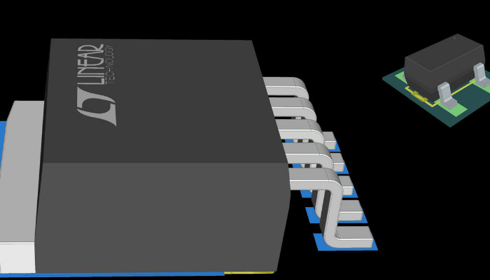
In many designs, you need a range of DC supply voltages. Usually, you create these using DC-to-DC converters. Old-style linear regulators aren’t really a good idea except where the power they supply is tiny. A linear regulator often has a big metal body. That’s because they “flare off” a lot of waste energy. A modern “buck” regulator, by contrast, is much more efficient – usually at least 80%. But buck converters need careful layout because, DC or not, they use high frequencies and are layout-critical. More efficient means less waste heat.
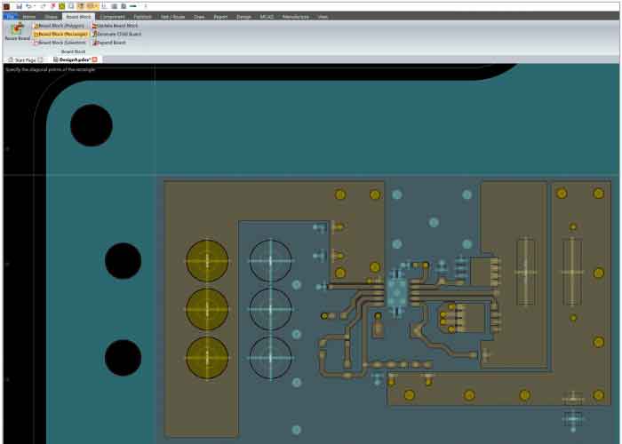
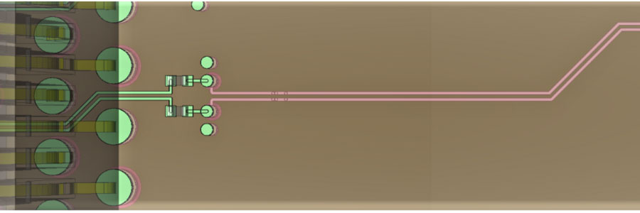
Once you have a proven DC-to-DC converter layout it’s a good idea to keep it for re-use. You’ve already done the work to pick an efficient design and you know the layout doesn’t introduce EMC issues. I framed this one and created a block in eCADSTAR PCB Editor. I saved this as a mini PCB design that I can share with other engineers, so they can just browse to it and drop it into their PCB layout.
High-speed signals in eCADSTAR
Signals affect power consumption in obvious and less-obvious ways. Let’s dig for a few less-obvious ways.
You’ve got a bank or two of SDRAM, but you don’t really need DDR4 and you have a stock of DDR3.
This is where POD (Pseudo Open Drain) makes a difference. DDR4 data signals (DQ) use it. Termination is ODT (On-Die Termination). 1.2V signals too – and lower voltage means less power.
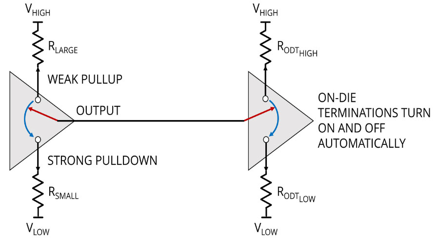
Traditional open-drain signals only drive one way (usually low) and the high state is created by a terminator to VCC when the drivers switch to open-circuit. These, like open-collector buses, were common before Tristate came on the market. When a driver on a bus went low, the bus went low and current was drawn through the resistor, in a quaint arrangement called “wired-or”.
So why has it reappeared in the form of pseudo-open-drain? Because of power consumption. Even better, we can lose the terminator current when the driver goes low, because the on-die termination only switches in on-the-fly, when it’s needed. It’s “pseudo” open-drain because there is a strong pulldown, but a weak, rather than absent, pullup at the driver. It’s more complicated than what I’ve drawn here, and it’s all done with semiconductors and DQ signals are bidirectional, but I hope this helps show the idea.
Really fast differential pairs follow a Layered Protocol. For example, PCI Express comprises seven layers. For power saving, I’ll just mention the one right at the bottom: Layer 1, the Physical Layer. Even then, there’s a load of extremely complex and clever stuff going on, like automatic spreading of RF content, encoding and data striping. But I’ll only talk about the most basic electrical bit and how it relates to power saving.: the popular choice of Low-Voltage Differential Signaling (LVDS). The power is really low – about 1.2mW delivered to the receiver – because it uses current-mode drivers. This just means that instead of signaling with a guaranteed minimum voltage, the drivers signal with a guaranteed minimum current.
It also generates really low EMI for reasons I might mention in another blog.
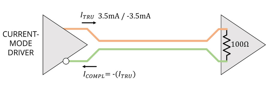
And serialization means that you can send a lot of information very rapidly over each differential pair, so it’s much more power-efficient than traditional signaling.
You can often configure I/O to use both different driver types and different driver strengths. It’s clear that, say, an 8mA driver uses more power than a 4mA driver and creates more crosstalk and power supply noise, so if 4mA is definitely strong enough, it’s better to use it. The Transient behavior is key here because current, voltage and power travel as waves in high-speed circuits. That creates noise and power blips when drivers (like leisure pool wave machines) deliver waves on to the PCB.
Finally
Cooling our planet just a tiny bit by cutting power consumption on our PCBs isn’t just green – it’s good engineering in all sorts of ways. As cool people say, “What’s not to like?”

-
Jane Berrie•Signal Integrity Expert, Zuken Tech Center, BristolJane Berrie has been involved in EDA for PCB signal integrity since the 1980s. Her articles have appeared in many publications worldwide - too many times to mention. Jane is also a past session chair for 3D IC design at the annual Design Automation Conference. Jane’s also an innovator with a unique perspective, who constantly works on new solutions in the fast-evolving world of electronic design. In her spare time, Jane has organized themed charity events - including two in aid of lifeboats and red squirrel survival. Jane is also a regular disco-goer.
A new internet-connected PCB design platform. Get a 30-day eCADSTAR evaluation licence with full features.
REQUEST EVALUATIONReady to brush up on something new? We’ve got more to read right this way.

- Products
March 11, 2024
What's New in eCADSTAR 2024.0
Key highlights of the eCADSTAR 2024.0 update
Read now
The 2024.0 update allows you to meet the increasing demand for compact, high-performing and energy-efficient electronic designs.

- Design Bureau
- VISIT WEBSITE
February 05, 2024
MMD - Modern Micro Devices
Design Bureau
- Blog
February 01, 2024
Power Integrity in PCB Design
Read more.
Read now
Power integrity is a critical stage of successful PCB design. Employing a diverse range of strategies and tools is essential for any designer.
- Blog
November 13, 2023
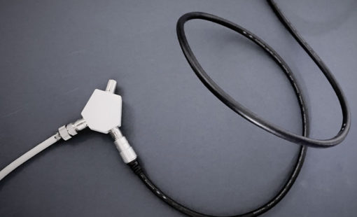
An Introduction to Time Domain Reflectometers
The TDR has been around for a long time. It’s standard equipment for many engineers, including telecommunications and home broadband installers.
Read now
Time Domain Reflectometer analysis in eCADSTAR’s Signal Integrity Advanced creates results similar to a TDR with simulation. Read More.