
eCADSTAR Schematic Block Hierarchy for Optimum Re-Use
Part-Based, Function-Based, and Block Symbols
Components you add to your schematic come from your library or from online partners, as do their symbols. You can have alternate symbols in your library too. These symbols can represent functional information as well as information about the part itself.
For example, if a component has configurable I/O banks, you can create library symbols for each one, together with their individual supply voltages. This works well if you start designing your PCBs before the I/O allocation has been finalized.
But schematics, and especially those for mixed technologies, often start with a block diagram and you want that to be as clear as possible. The symbols you need for that can be specific to your design or to a group of designs. Schematic Editor’s multi-instanced hierarchy blocks are ideal for that and you can export them to use in other designs.
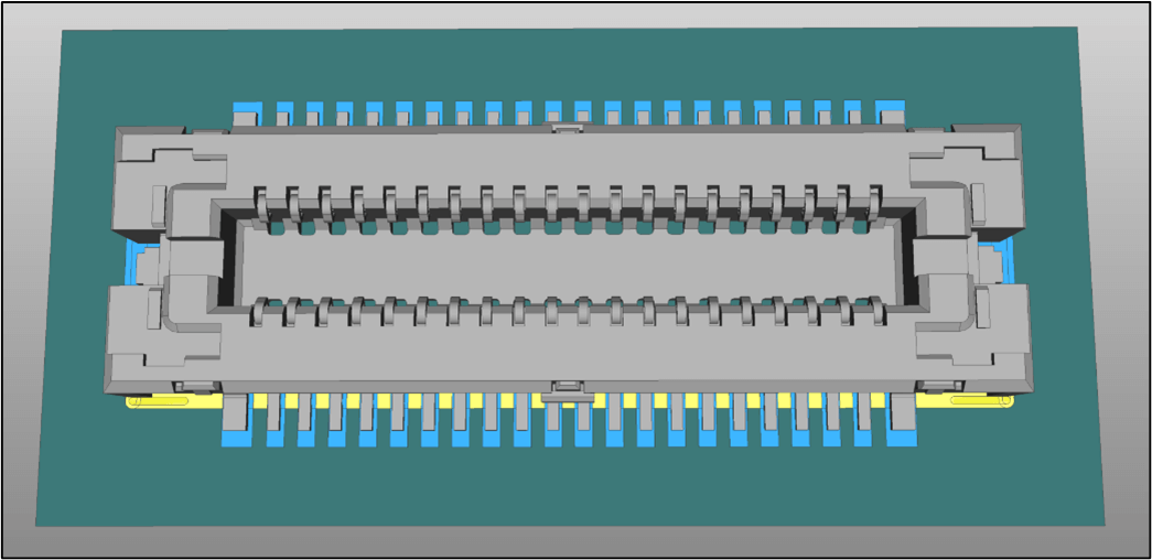
You can save hierarchy blocks in your own local “library”. For example, you can use the connector shown in Figure 1 for either a D-PHY or C-PHY physical interface layer.
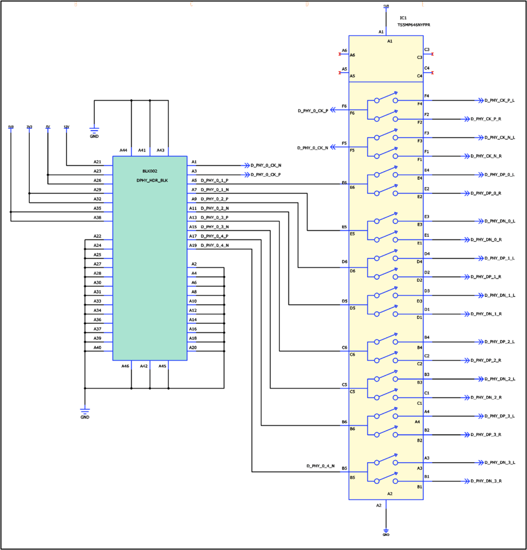
For D-PHY there is a separate differential clock and three differential pairs for the data, so the data pairs are arranged on the block symbol so that the differential connections are in sequence (Figure 2).
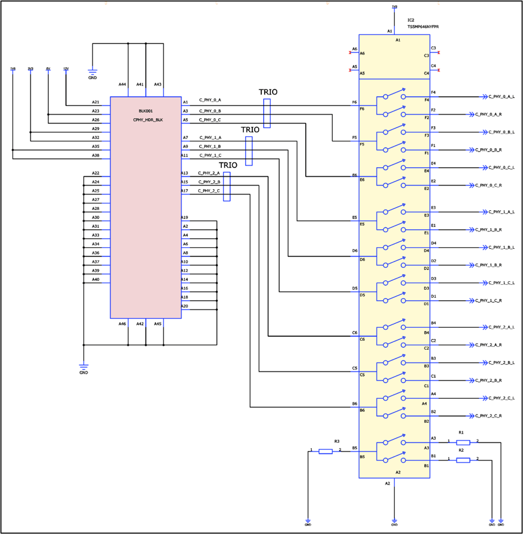
For C-PHY there are three signal TRIOs. TRIOs are used to implement a more sophisticated kind of signaling that is still differential, but with dynamic allocation and clock encoded within data. In this case, each of the three TRIOs are grouped together in the right order, using the block symbol to wrap the connector’s library symbol (Figure 3).
The same library symbol underlies the blocks for both D-PHY and C-PHY. Components you add to your schematic come from your library or from online partners, as do their symbols. You can have alternate symbols in your library too if you want to make different function-oriented symbols that your whole team can use.
Getting the Most from Multi-Instanced Block Hierarchy
You can use hierarchy blocks to save re-entering data in many ways, and to structure schematics for maximum clarity. You can save any block definition, at any level, to re-use in other designs.
How could we use block hierarchy to get the most from the DDR4 circuit in Figure 4?
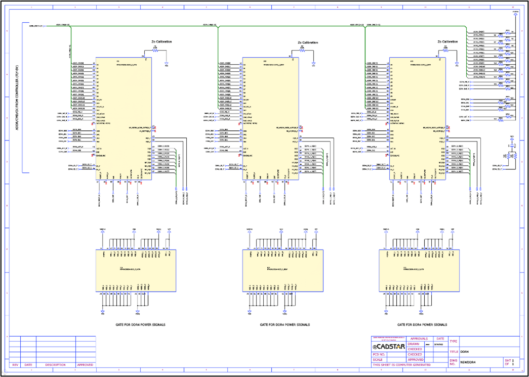
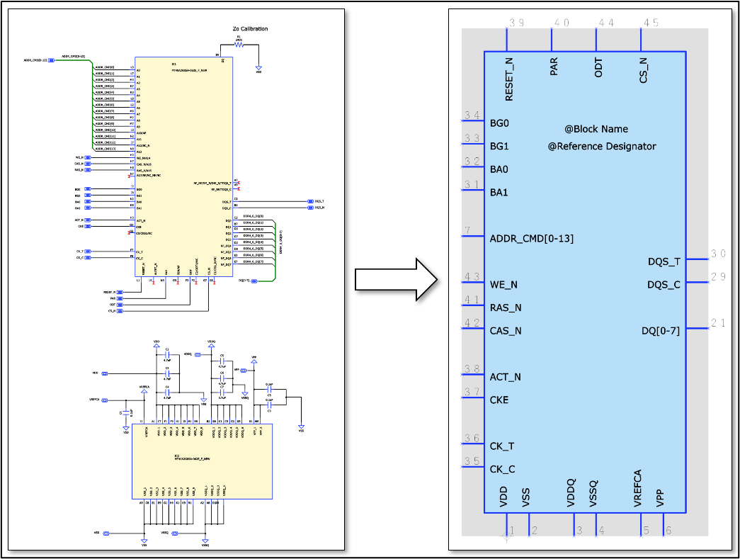
Here is a block definition for a single DDR4 device and its local decoupling capacitors and Zo calibration resistor (Figure 5). These are the same for any DDR4 device, within this design at least, so creating a block makes all this easy to re-use.
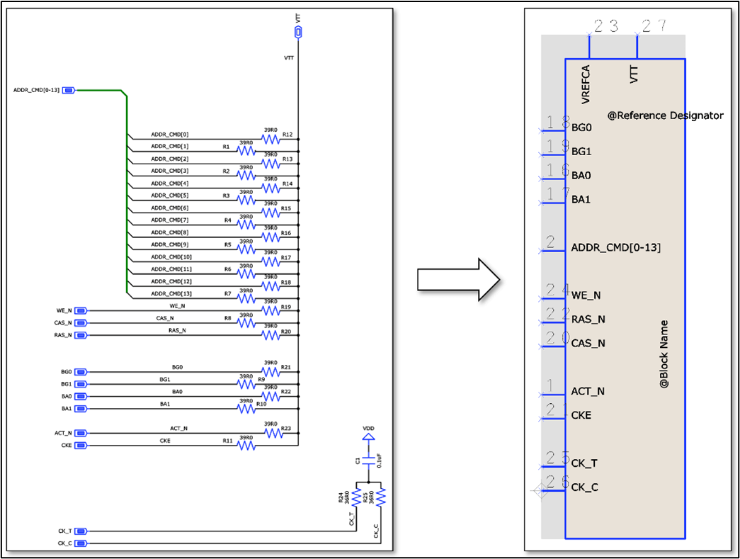
The DDR4 devices in this design are routed in a Fly-by topology with the terminators at the end of the chain, as defined by the JEDEC specification, so we can make the terminators a block too (Figure 6).
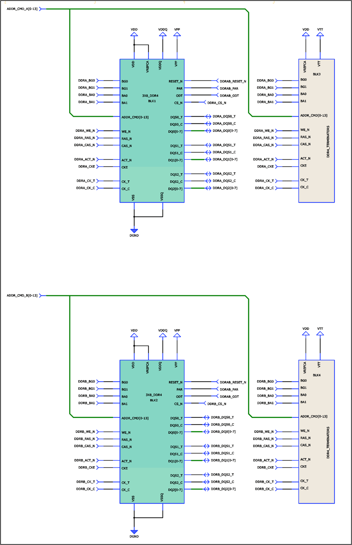
Finally, creating a block for three chained DDR4 devices and adding two instances of that block to the main schematic, makes the circuit (Figure 7) easy to interpret, without the duplication that would be needed in a flat design.
Seeing into the Future: What about ECOs?
Although our schematic designs seem right when we enter them, engineering changes come along for all kinds of reasons. It can happen during schematic entry, later in the design process, post-production, or when a schematic circuit has been re-used in different designs.
This is where considering those future “game” moves is so important. The impact of an ECO should be limited to the changes it introduces, without affecting components or connections that aren’t involved.
Multi-instanced block hierarchy, in contrast to single-instanced, requires a little more upfront consideration. There are many ways to do it, but I’ll describe my method and why I choose to do it this way.
There’s a big difference between a block definition and a block instance, especially where there are multiple instances of the same block. There are special considerations when it comes to reference designators.
Within each block definition, you can assign a reference designator to each component, but you can see that if you created two instances of that block, then those reference designators would be duplicated within the schematic design. You could of course auto-assign all the reference designators on the block instance schematic sheet, but that doesn’t work so well for a later ECO within the block definition.
I decide on a standard increment for reference designators within each instance schematic sheet. This means that the relationship between the block definition components and the instance components remains clear, and ECOs have minimum side effects.
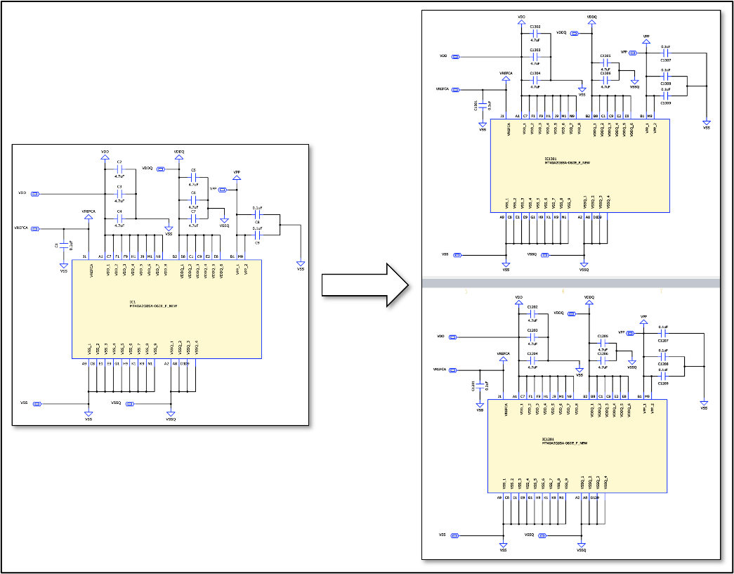
For example, in the two block instances shown in Figure 8, C5 has become C1205 and C1305 respectively. Even if I later add a component in the block definition, I can simply give it a new, unique reference designator within that definition. When the change propagates to its block instances, I can add the same increment as before and only the new component’s reference designator will be affected, making it easy to review and process the ECO.
Summary
Multi-instanced hierarchy reveals the underlying structure of designs and makes schematics easier to read and review. It’s also great for re-use, because key parts of the circuit are separated into re-usable blocks that you can use in multiple designs. You can group components within each block instance to make them easy to identify and place when it comes to physical design. Then you can copy relative component placement from one block instance to another. Planning for optimum ECO handling from the outset yields a smooth experience further down the line, while keeping all the benefits that multi-instanced block hierarchy brings.

-
Jane Berrie•Signal Integrity Expert, Zuken Tech Center, Bristol.Jane Berrie has been involved in EDA for PCB signal integrity since the 1980s. Her articles have appeared in many publications worldwide - too many times to mention. Jane is also a past session chair for 3D IC design at the annual Design Automation Conference. Jane’s also an innovator with a unique perspective, who constantly works on new solutions in the fast-evolving world of electronic design. In her spare time, Jane has organized themed charity events - including two in aid of lifeboats and red squirrel survival. Jane is also a regular disco-goer.

- Blog
Jane Berrie teaches you how to use the eCADSTAR Library Editor and to re-use design data effectively
- Datenblätter
eCADSTAR Schematic Editor ist eine effiziente und intuitive Anwendung zur Erfassung von Schaltplänen, die zur Definition von Bauteilkonnektivität, Varianten und Design-Constraints zur Verwendung im eCADSTAR PCB Editor eingesetzt wird.

- Products