
CADSTAR Signal Integrity
TOP FEATURES AND BENEFITS
- Integrated within CADSTAR HighSpeed Design suite for concurrent and post-layout SI analysis and constraint
verification. - Accurate transmission line analysis for fast calculation of reflection and crosstalk effects.
- Embedded simulation model library includes standard IC models and an IBIS 5.0 parser.
- Support for eye diagrams, frequency domain/S-Parameter simulations, and parameter sweeps.
- Time domain analysis supports frequency-dependent “skin effect” and Ohmic losses for accurate simulation into the GHz domain.
- Perform virtual measurements at the IC package pin or directly on the silicon die.
- Frequency domain simulation supports S-Parameter and transmission line impedance, with the option to export S-Parameter data in Touchstone format.
Introduction
As more designs incorporate high-speed technologies and involve integrated circuits (ICs) with rapidly increasing fast edge rates, the need for signal integrity analysis has become a vital part of the product development cycle. Signal quality is an important factor in the performance of the overall product, so the need to analyze crosstalk effects, over/undershoot, propagation delays and the evaluation of different termination schemes can help identify problems early in the design process, and avoid unnecessary design failures and costly iterations.
High-speed interfaces such as DDRx and PCI Express demand complex timing requirements that cannot be resolved by applying traditional rules of thumb to secure effective signal quality. CADSTAR SI Verify offers a complete concurrent and post-layout signal integrity solution that enables engineers, layout designers and specialists within a development team to collaborate, organize, constrain, and verify their design in a seamless process. This helps them work more effectively, minimize costs, and improve overall time to market.
Design management and navigation
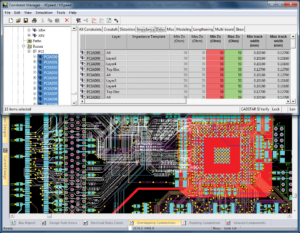
CADSTAR SI Verify utilizes the constraint manager spreadsheet-style interface to simplify design management, classification and constraint entry.
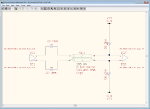
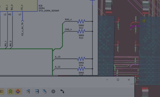
From the constraint manager, easily generate simulation results within the SI Simulator (waveform viewer) or directly populate the constraint spreadsheet with simulation and measurement results. The design tree view simplifies management and classification of nets and components within a design, and provides easy access to conduct “what-if” analysis to study and determine best strategies for signal termination and topology. CADSTAR SI Verify includes a standard library of IC models. You can import or build your own models using IBIS, SPICE sub-circuit, or user-defined transmission line/ lumped element models to support accurate analysis of critical signals in your design.
Layer stack-up definition
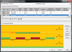
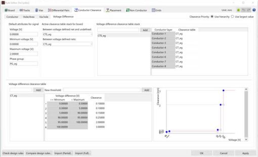
The layer stack-up can be modeled to determine the characteristic impedance of critical transmission lines, accommodating track profile for both rectangular and trapezoidal mode, enabling either the embedded finite element method (FEM) or boundary element method (BEM) field solver and advanced construction materials to achieve accurate results. Frequency-dependent losses and induced crosstalk for coupled lines are included for enhanced accuracy at higher frequencies.
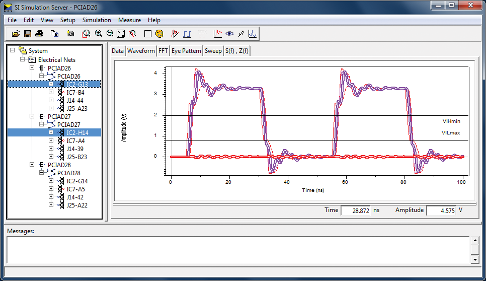
Interactive and batch simulation
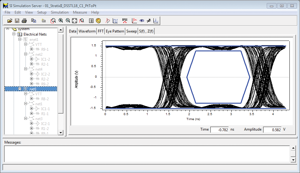
CADSTAR SI Verify works in both time and frequency domain modes to analyze transmission lines parameters and provide fast analysis of reflection and crosstalk, in addition to measuring timing and delay characteristics. You can run interactive or batch simulation for single or coupled lines, returning a range of graphical results including:
- Voltage over time
- FFT (Fast Fourier Transformation) to identify frequencybased hot-spots
- Fast eye diagram generation
- Frequency-domain analysis for transmission line impedance and S-Parameter results of the whole interconnect
- Parameter sweeps for discrete values, trace parameters and driver/receiver models for expanded analysis of highspeed interfaces, such as the optimization of on termination (ODT) settings
- Easy-to-use interactive and automatic measurement tools to capture critical points, such rise/fall time and over/ undershoot
 CADSTAR Signal Integrity – Datasheet
Ready to brush up on something new? We’ve got more to read right this way.
- Solutions
Heute aufrüsten
- Seiten
Die Prüfung und Identifizierung der Quellen von Signalintegritätsproblemen und Ihre Behebung ist eine große Herausforderung.

- Seiten
Analysen zur Optimierung des Verhaltens von High-Speed PCB-Deisgns

- Datenblätter
Sie können die Signalintegrität in jeder Phase vom Schaltplan bis zum PCB-Layout planen und überprüfen. Wo auch immer Sie dies tun, die Ergebnisse werden auf die gleiche Art und Weise präsentiert und das Look and Feel ist immer gleich.