creepage and clearance banner

What is New in eCADSTAR 2021

eCADSTAR offers all that and is moving ahead with you—refining, tuning, enhancing—so your electronic engineers and PCB designers can work even more accurately and efficiently.
Menu

This has been a time of change for everyone. In 2021, some things will be as they were before, but some will be different. In the world we live in now, you need fully-connected, efficient EDA.

Check Creepage Rule Compliance in 3D

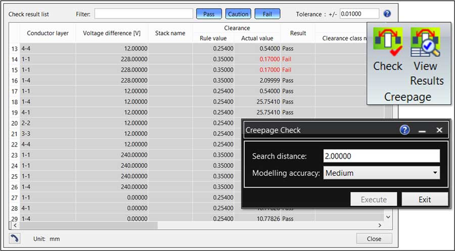
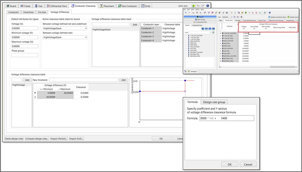
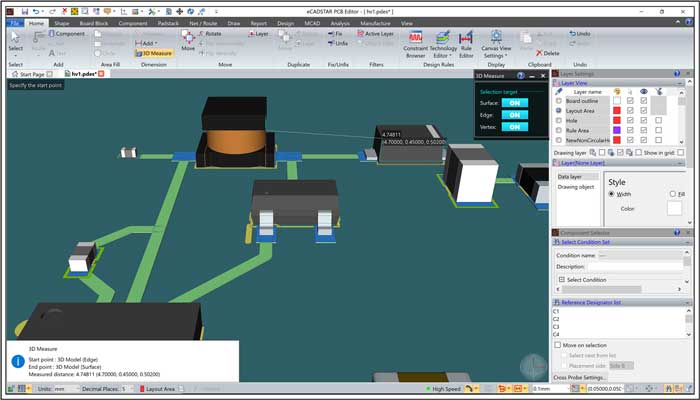
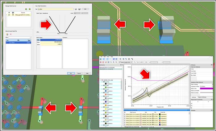
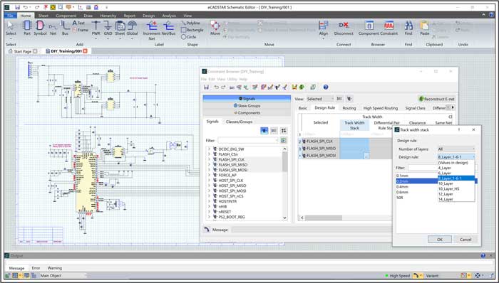
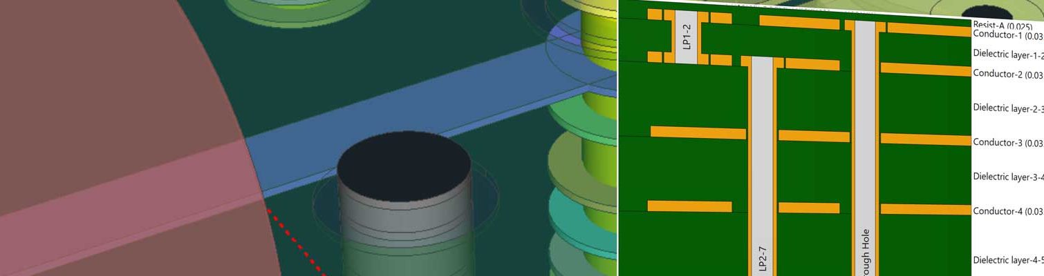
Check for creepage in 3D based on voltage differences and standards (eCADSTAR Advanced 3D and Ultimate only).

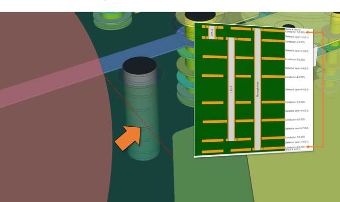
2D clearance is always less than or equal to 3D clearance; but working to 3D creepage rules means you can design more densely, because clearance is measured by its true path. For example, making a slot in the PCB can allow other components to be placed more closely to a high-voltage avalanche diode bias supply.

Learn More

2D/3D clearance

electrical safety_eCADSTAR2021

Check electrical safety. Particularly important for designs with high-voltage routing such as LIDAR. Cross-probe to the canvas and view in 2D or 3D with traffic-light Pass, Caution, Fail color coding. 

SPICE Simulation Control – Available with eCADSTAR 2021.1

Control SPICE simulation from Schematic Editor

The eCADSTAR SPICE controller will provide a tightly integrated engineering solution for easy simulation of analog circuits within eCADSTAR Schematics, making eCADSTAR a single point for PCB design and simulation.

Engineers will be able to view graphical waveforms, conduct what-if analysis, change discrete component values and sweep simulation parameters using an embedded version of the free high-performance simulation software LTspice® from Analog Devices.

Learn More

Productivity Improvements

Integrate external applications, adding them to the Quick Access Toolbar, so you can launch them without leaving eCADSTAR. 

eCADSTAR_2021.0_report

Now, if you select “Open Report in Excel”, a report in Comma-Separated-Values format called “report.csv” is opened as a spreadsheet, replacing multiple steps with just one.

You could already configure your own reports. Now make them accessible directly from eCADSTAR.

user report parameter file_eCADSTAR2021.0

Once you add the path to a user report parameter file (.prgx), you can select it for generation from a dropdown list.

You can decide where to access user commands, both when you create them and when you edit them.

edit a user command_eCADSTAR2021

When you add or edit a user command, you can decide where to make it available for selection.

Now you can select power, ground, sheet connector, hierarchy connector and global signal symbols directly on the ribbon.

hierarchy connector_eCADSTAR_2021

You can select symbols directly on the ribbon in Schematic Editor – a great time-saver, because engineers use these symbols a lot – often many times, even on the same sheet.

Now you can import DXF drawing data created by mechanical CAD systems in both Library Editor and Schematic Editor.

DXF drawing data

DXF is a widely-used industry format in mechanical graphics applications. You may already have logos or symbols in that format. Now you can import them instead of redrawing them.

Keep design information directly within schematic design data for reliable future reference.

unique design-related information

Enter unique design-related information directly with automatic recording of creation and modification times.

Customize sheet number format.

Customize sheet number format

Customize sheet numbering format and reflect block hierarchy.

Configure and display enriched cross-reference information on sheet connectors.

enriched cross-reference information

You can configure the cross-reference format from the ribbon.

Optionally omit “I” and “O” from zone letters to conform to standards or to avoid confusion with one and zero.

Optionally omit “I” and “O”

You can omit characters “I” and “O” from zone letters if you wish.

Import EDIF schematic data.

Import EDIF 200 data

Import EDIF 200 data so you can re-use IP from more external sources.

Usability Improvements

Save and load views in Schematic Editor

Play

Change angled trunk corners into curves and adjust radii on the PCB Editor canvas.

Curved trunk corners can improve stress resilience and smooth-out track-to-track coupling discontinuities. Direct interactive editing means you can see exactly what kind of corner you are getting in real time.

Move (or duplicate move) trunks with full corner and via pattern retention.

Move, flip and rotate trunks with no loss of via patterns or trunk geometry. You can do the same with duplicate-move, providing fast, easy re-use of trunk patterns for maximum PCB design consistency and symmetry.

Measure true 3D distances without extra calculations.

Measure true 3D distances_eCADSTAR2021

The world is three-dimensional, so why measure in 2D? Measure it like it really is in your PCB design.

High Speed Enhancements – Available with eCADSTAR 2021.1 

Impedance balanced routing

Route differential pairs obeying multiple width and spacing rules in the applied topology template.

Impedance Balanced routing allows for increased impedance control of differential pairs required to support today’s high speed PCB technology requirements.

As well as support during your interactive routing process, it is possible to retrospectively update existing differential pairs to respect new width and spacing requirements.

Impedance-balanced-routing-300x183


interactive re-lengthening ecadstar pcb

Interactive Re-lengthening

The Activ-45 router, Trunk routing and Interactive lengthening are now able to re-lengthen to meet a minimum length on constrained nets. This feature is supported as part of the routing, or modification of the net.

Power Integrity Analysis Enhancements

Override package-based parasitic models.

Decoupling capacitors come in many package styles and all of them create different parasitics. Experiment easily, by swapping package-based models without the need to change design data. A bit close to the voltage limits with that decoupler? How about changing it to a 25V? That’s in a bigger package, but will its parasitics give you a problem?

Easily identify high-current vias. 

high-current vias

High-current vias harm power integrity. Need a bigger via? Need an extra via? The high DC current in this via is revealed by sorting the column on via current. You can then adjust or add vias in PCB Editor (shown above the Power Bus window in this image).

Configure cell buttons.

Radiation window

This button in the Radiation window has been configured to display the spectrum. Alternative functions are still available on the right-mouse-button menu.

Set impedance masks to check and measure against expected power bus impedance in PCB design.

impedance masks to check and measure_eCADSTAR_2021

Presented in a similar way to eye masks, impedance masks mean you can check potential local impedance hotspots against the expected impedance over a range of frequencies.

Reduce aliasing noise with windowing.

Fast Fourier Transform (FFT) sampling _eCADSTAR_2021

Fast Fourier Transform (FFT) sampling is designed to work with a round number of complete waveform cycles. This is not always the case and aliasing can make results unreliable. Windowing techniques like the Hann window function counter this effect.

And when you have some frequency domain results, you can now configure a cell button in Analysis Result Viewer to view them more easily.

Analysis Result Viewer

Configure a cell button for frequency-domain mode.

Design Rule and DRC Enhancements

Choose PCB layer stack directly from Schematic Editor.

PCB layer stack PCB layer stack

Layer stack decisions are often made before or during schematic entry. You can make those decisions right here in Constraint Browser as your design takes shape.

DRC options are saved and selected by default next time you work on a schematic.

DRC options_eCADSTAR_2021

As schematic entry progresses, the DRC check options usually progress. Now you don’t have to reselect those options each time you launch Schematic Editor.

FIND OUT MORE

Why not request a free eCADSTAR 2021 demonstration? Discover how eCADSTAR is now even more powerful and user-friendly than it was in 2020—enriched with real-world features so you can design even more quickly and reliably.

Try eCADSTAR for Free

Start a 30-day free trial with a full-featured evaluation license with no technical limitations. Achieve your PCB design goals today.
Request Evaluation