eCADSTAR Signal Integrity 2020 Release

Signal Integrity Analysis in PCB Design

Simulate, measure, share results independently of PCB design.
Menu

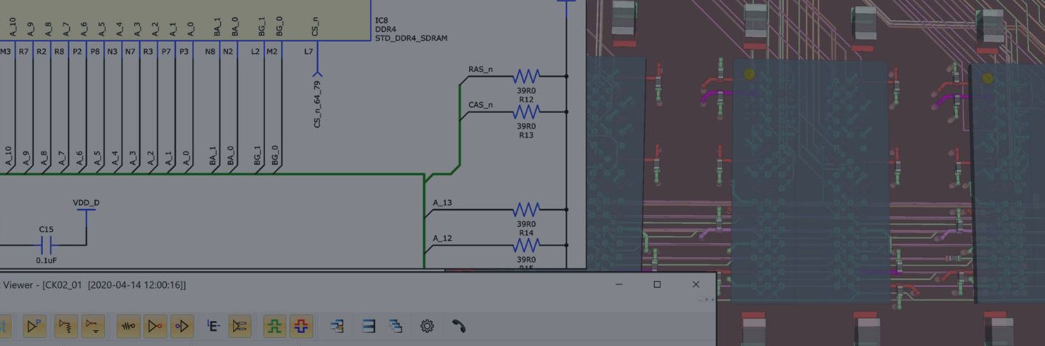
EMBEDDED SIGNAL INTEGRITY ANALYSIS

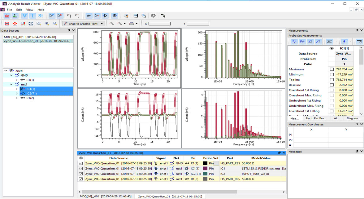
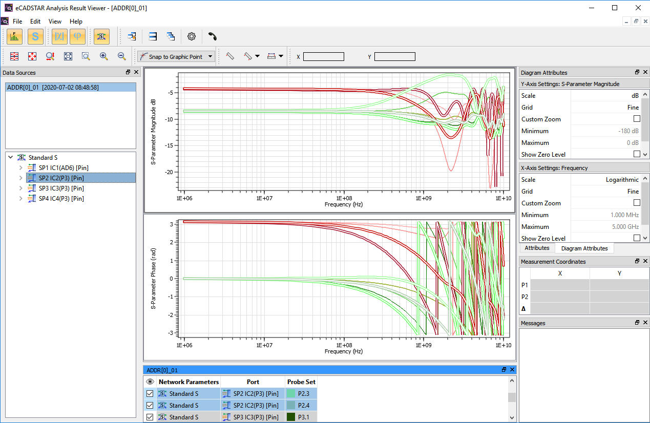
Signal integrity analysis is embedded into the eCADSTAR Schematic and PCB Editors providing pre-layout and post-layout simulation capabilities.

  • Simulate, measure, share results independently of PCB design.
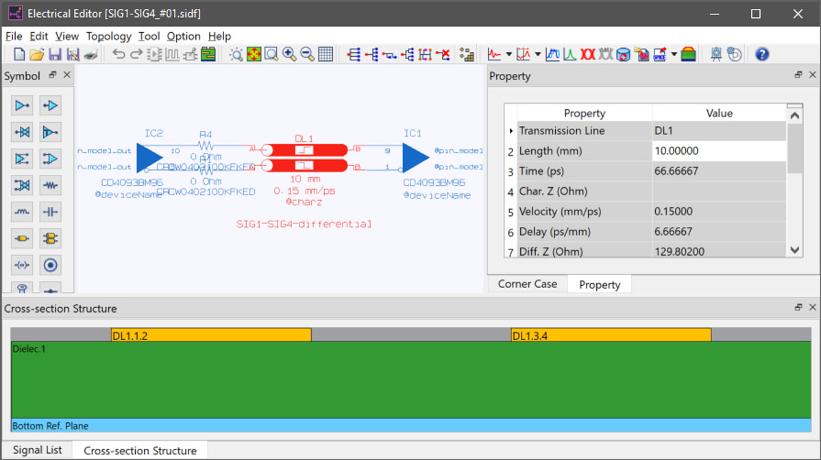
  • Constrain and plan topologies in the pre-layout phase.
  • Plan impedance using the integrated field solver using lossy interconnect models.
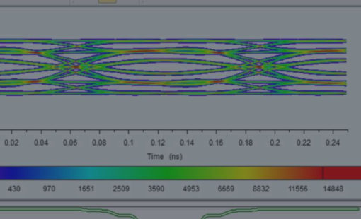
  • Analyze signals in the time domain.
  • Automatic measurement for key distortion and timing parameters (e.g. slew rate) allows fast error detection.

signal integrity analysis after the Signal Integrity simulation for your pcb design using the eCADSTAR analysis result viewer for signal integrity definition and SI analysis

ANALYSIS RESULT VIEWER

Signal integrity analysis in pcb design with the electrical viewer for signal integrity definition and SI analysis

ELECTRICAL EDITOR SCENARIO

WHAT-IF ANALYSIS

Perform what-if analysis to optimize high-speed performance

Electrical Editor:

  • Extract equivalent electrical topologies based on physical PCB design data (routing and placement).
  • Extract coupled/uncoupled transmission line structures with user-defined parameters.
  • Detect return path discontinuities by considering true reference plane shapes including routing over cut-outs on reference layers.
  • Extract via models (complex vias) and consider back-drilling.
  • Consider same-layer reference conductors (Co-planar extraction).
  • Perform impedance studies by changing cut-sections in the field solver.

SIGNAL INTEGRITY ANALYSIS ADVANCED

Signal integrity analysis advanced for very high-speed design. Builds on the functionality that the Signal Integrity option delivers and adds even more functionality.

  • Derive S-parameters for topologies that you have extracted and edited in Electrical Editor.
  • S-Parameters allow modeling passive interconnect behavior in frequency-domain (derived from measurement or like in eCADSTAR by simulation). S-Parameter export from the Electrical editor handles modeling of passive circuit elements only.
  • S-Parameters describe coupling and transmission behavior of a system for a wide frequency range. Issues at high frequencies which for example may cause crosstalk can be identified, quickly.
  • TDR (Time-Domain-Reflectometry) analysis sends a fast pulse down the PCB trace and displays the returning reflections, which indicate changes in impedance. This allows estimating signal integrity performance without the need to have IBIS buffer models assigned.

Signal integrity analysis in pcb design with the S-PARAMETER RESULT (MAGNITUDE AND PHASE) for signal integrity definition and SI analysis

S-PARAMETER RESULT (MAGNITUDE AND PHASE)

ADDRESSING A COMPLEX PROBLEM DOMAIN

To support all relevant high-speed requirements, the key high-speed design issues are:

  1. Impedance control.
  2. Skew/length matching & topology control.
  3. Rule Definition for high-speed routing (e.g. pin-pairs, impedance, max number of vias).
  4. Designing against these high-speed rules.
  5. What-if capabilities are needed (e.g. topology, terminations).
  6. Concurrent SI and PI analysis allows an immediate judgment of the electrical performance for design decisions.

LEARN MORE ABOUT THE IMPORTANCE OF SIGNAL INTEGRITY ANALYSIS

CLICK HERE

Try eCADSTAR for Free

Start a 30-day free trial with a full-featured evaluation license with no technical limitations. Achieve your PCB design goals today.
Request Evaluation